|
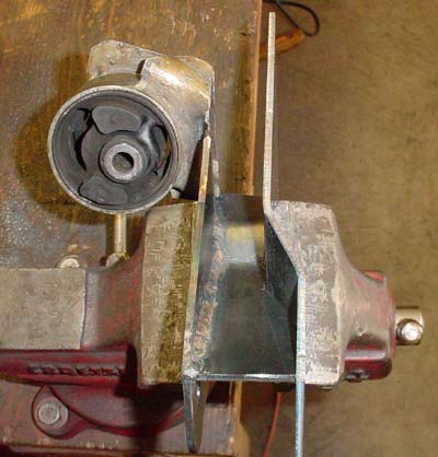
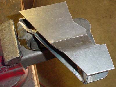
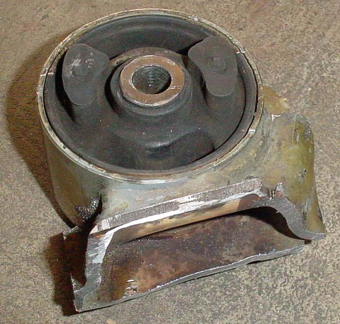
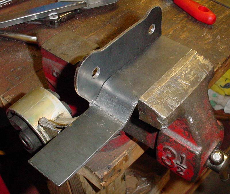
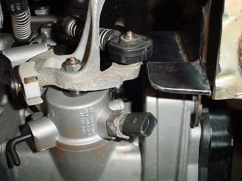
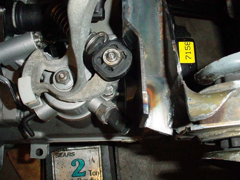
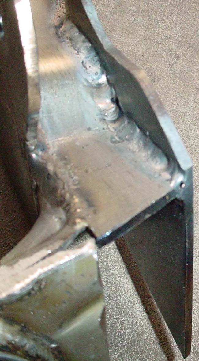
To allow for
shift linkage clearance, the horizontal piece was cut away in the
corner that was encroaching on the natural habitat of the linkage.
|
|
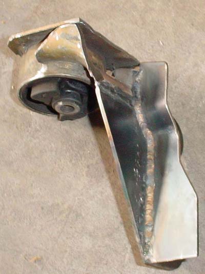
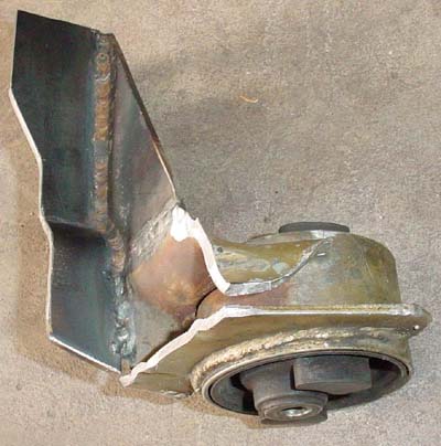
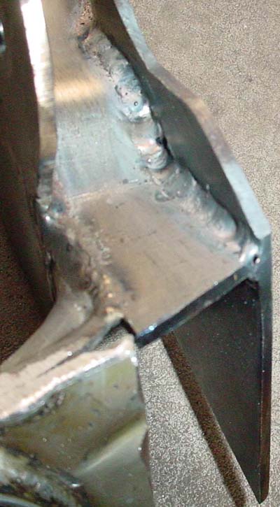
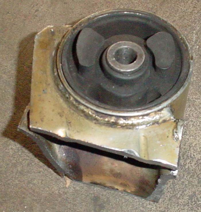
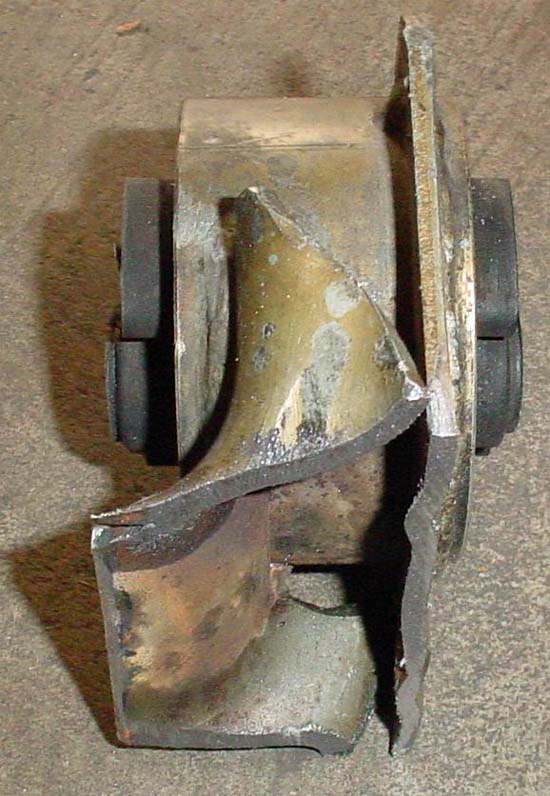
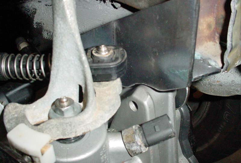
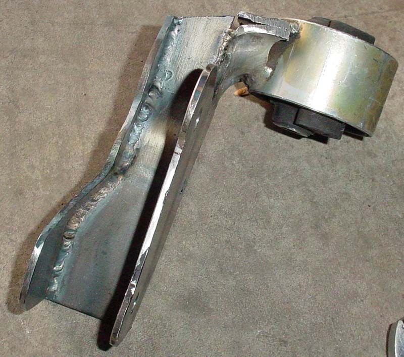
With clearance verified, the horizontal piece moves in permanently. These pics show the completed welding.
|
|
|
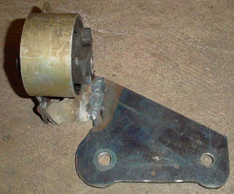
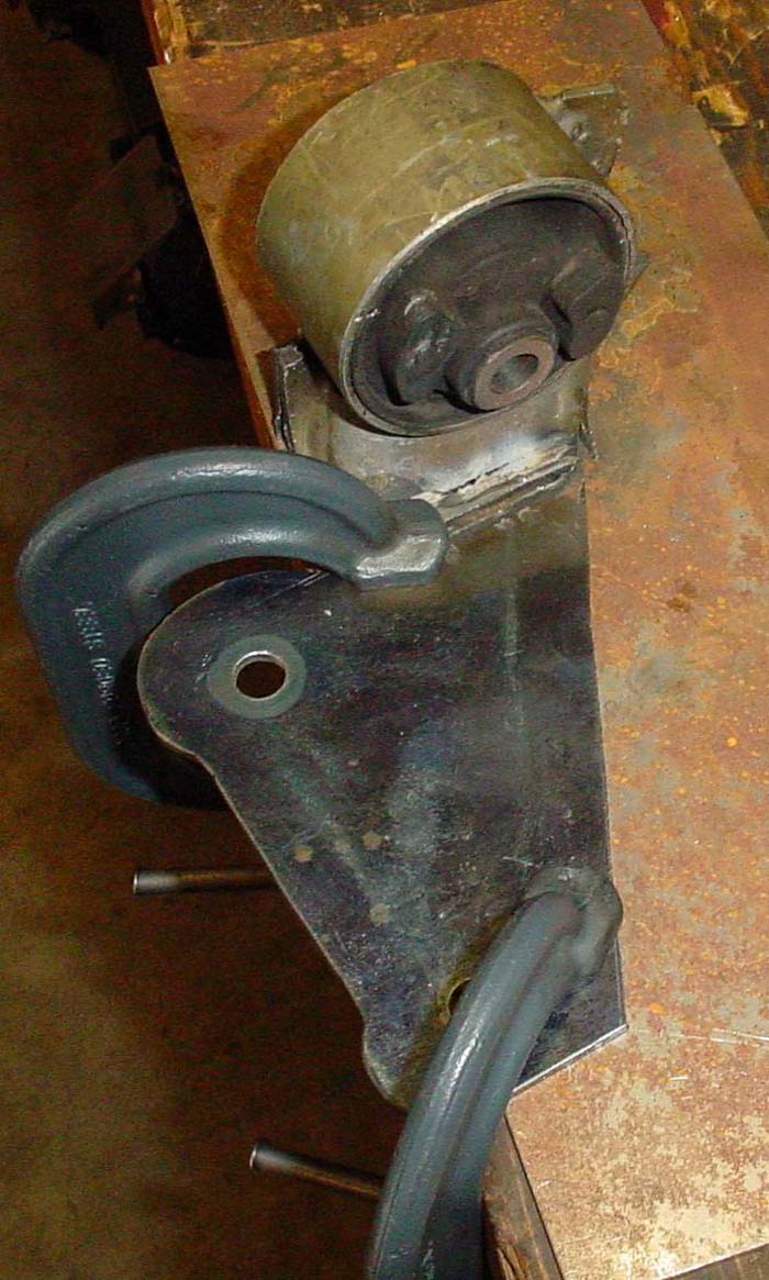
So, with the first two pieces happily living together....a third wheel
enters the mix: Vertical piece #2. The second vertical
piece will pick up the inside mounting hole of the rear tranny mounting
lug (since the inner edge of the front lug is not machined, only the
rear lug will be picked up on both sides) |
|
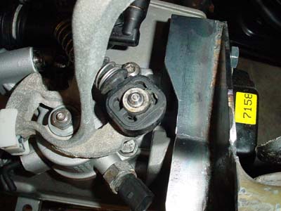
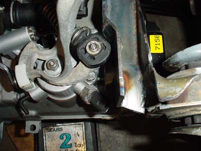
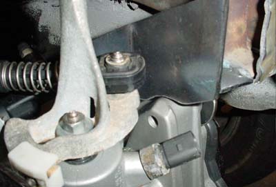
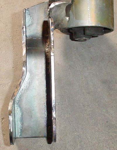
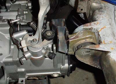
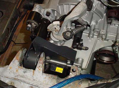
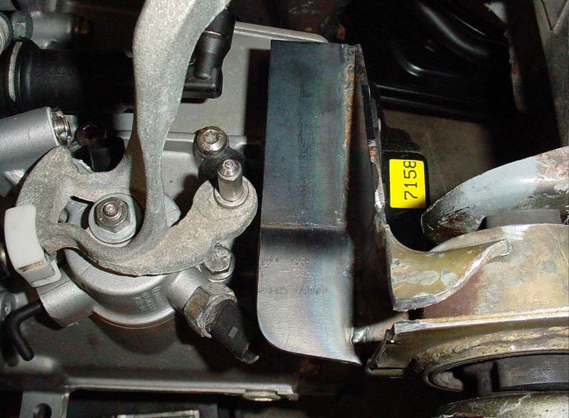
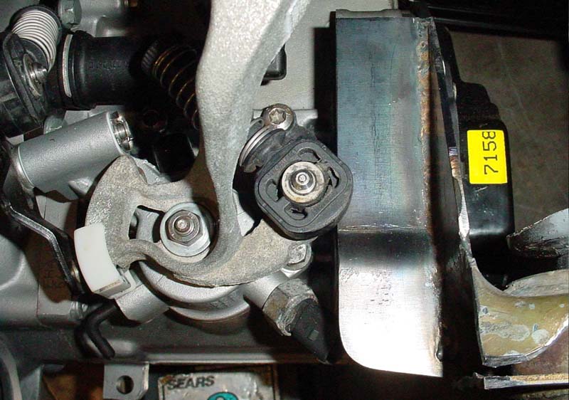
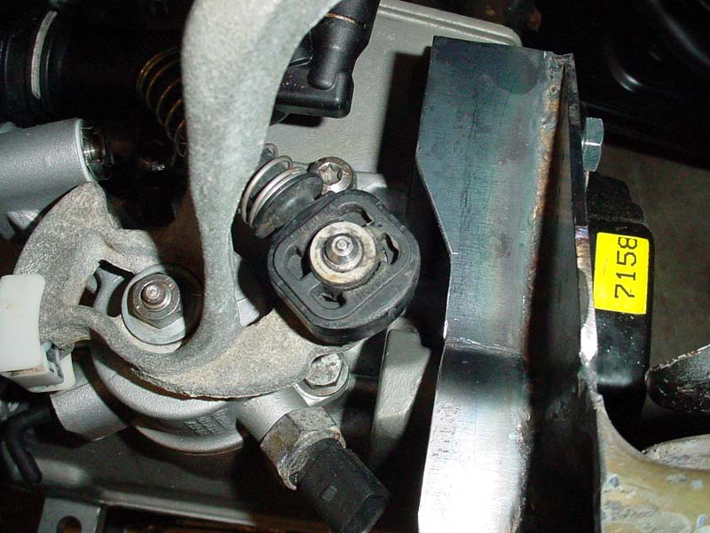
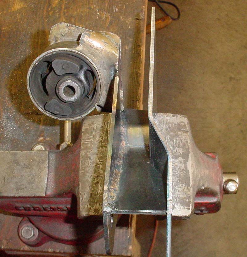
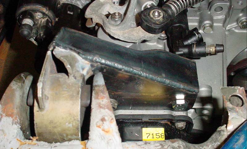
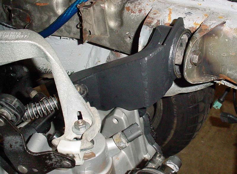
With tack welds in place, the mount is trial fitted on the tranny
|
|
Some cuts are made to clear the front of the tranny mounting lug and then back into the engine bay it goes!
(yup....good to go)
|
|
|
|
So,
with the trial fitting done with, it is time to weld this puppy in
place....or as it may be....weld this puppy in place as much as the
crevice will allow.....
|

|
....and this was the extent of the welding (for that side of that piece)
|

|
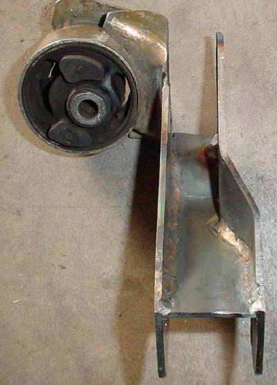
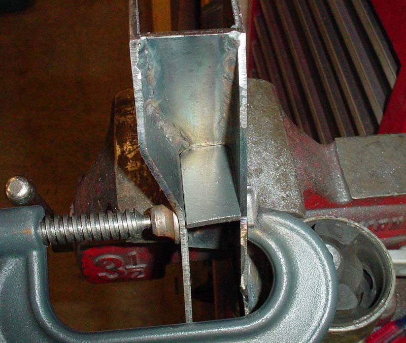
Enter....the internal stiffner.....It's sole purpose in life?? To stiffen things of course!!!!
|
|
......and
here we have Mr. Internal Stiffener all welded in place....note that it
does not have to be completely welded to be strong.
|

|
And now we finish up the welding on the outer vertical piece...
|
|
Same
view but shown to emphasize the level of difficulty in getting the
torch down in there......The tungsten electrode had to be extended
quite far. The thought was that if the top seam for the vertical
side member couldn't be fully welded..then come hell or high water at
least one of the other seams would be!
|
|
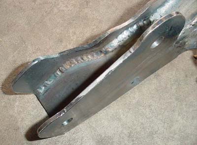
...and there you have it....all difficulties aside...that seam looks welded to me......!
|
|
|
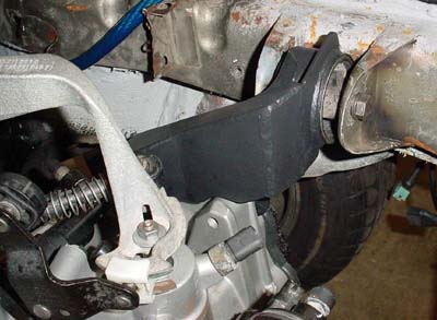
And....one more trial fitting.....and everything still looks good to go......
|
|
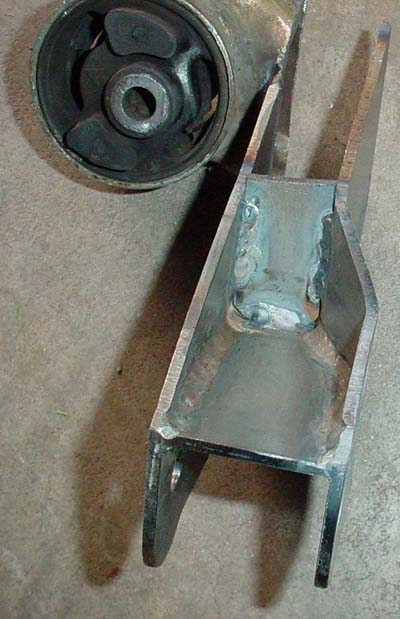
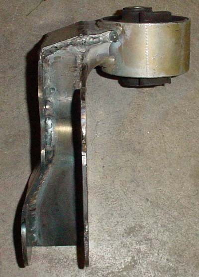
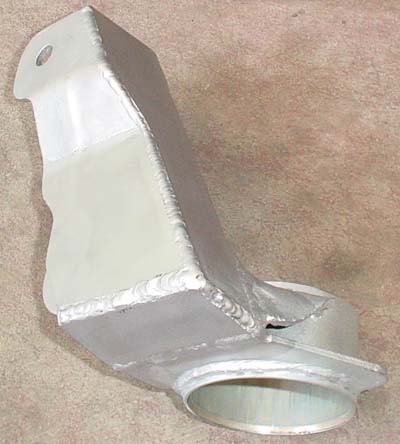
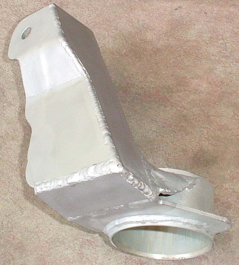
So now to put the final touches on the welding and tidy things up...
Here we see that the outer vertical piece has been completely welded on
and the internal stiffener ground down to the height of the vertical
pieces.
|
|
And here we have a view of the underside welding of the outer piece
where the welding extends over into the original mount to weld up that
seam.
|
|
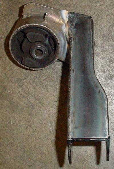
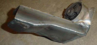
And finally.....here we have the top piece welded into place.
|
|
|
|
|
 |
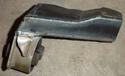
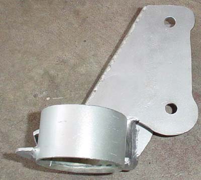
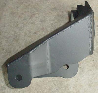
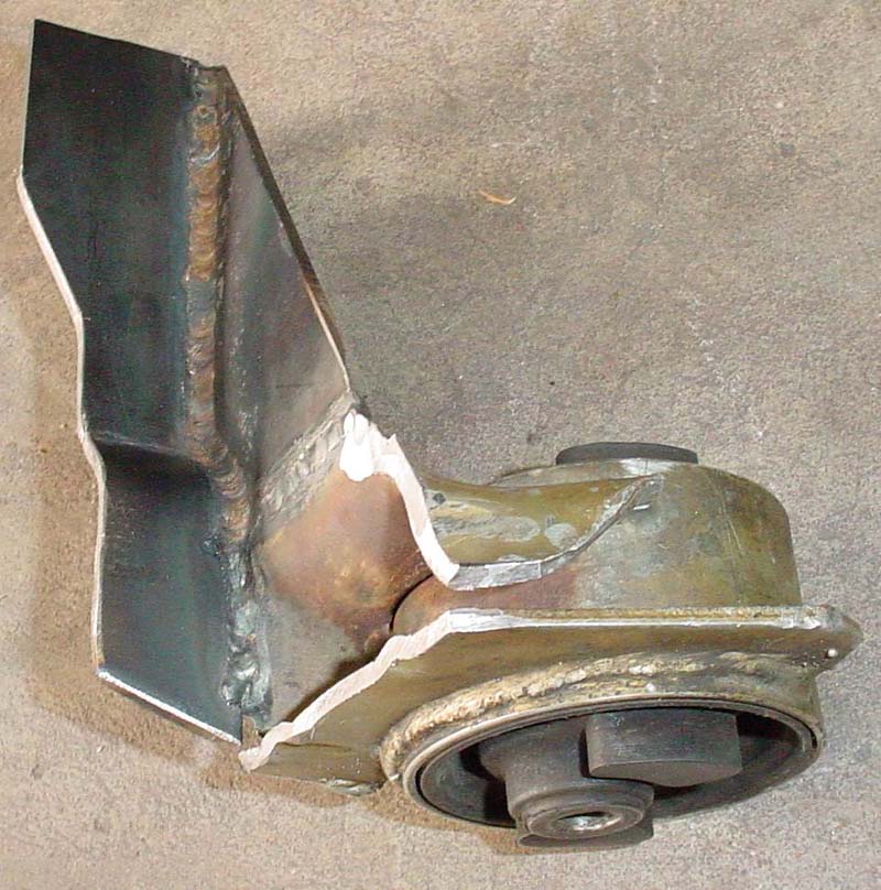
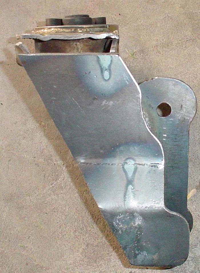
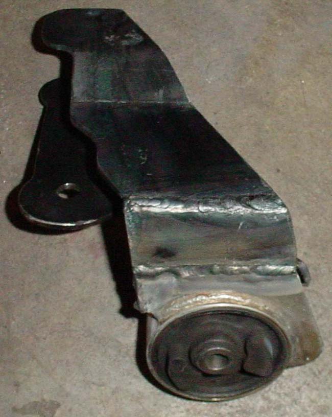
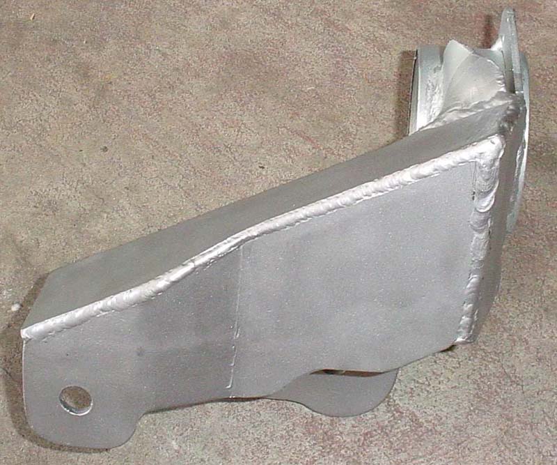
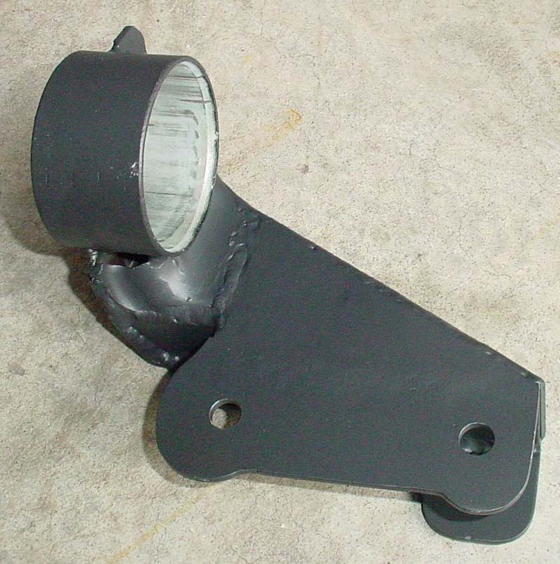
....and now we have a completed mount without the holes added....
|

|

|
The pics above show the final version, everything welded, happily
co-existing, and the holes drilled with the tranny side of the bracket
actually now attached to the tranny mounting lugs.
|
|

|
|
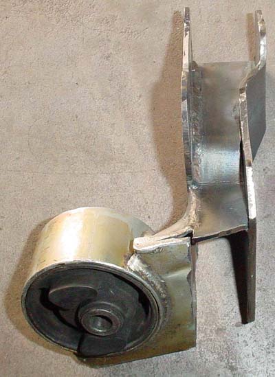
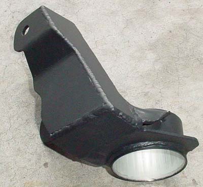
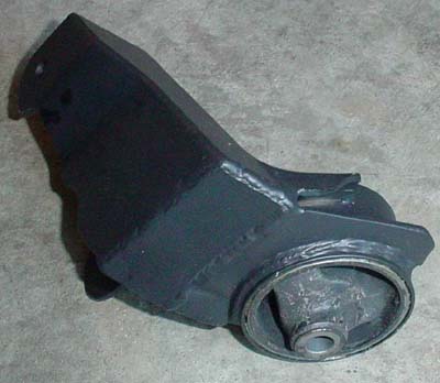
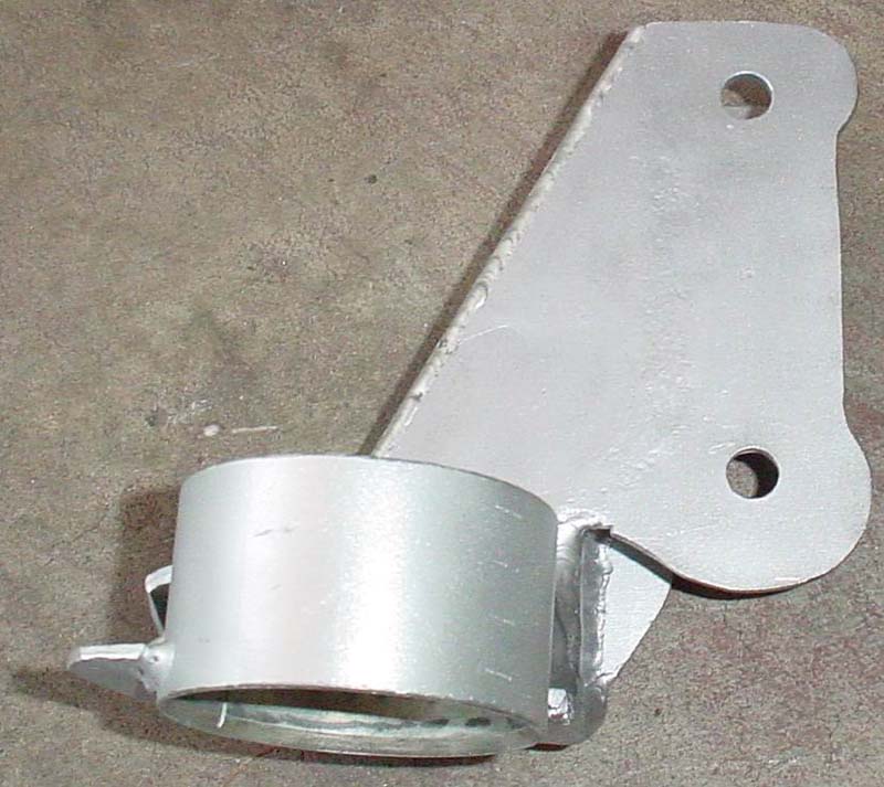
Welp,
you guessed it....these are pics of the newly fabricated driver's side
mount bracket, after it has been thoroughly bead blasted.
|
|
Then we have the powder coated version....now featured in...Flat Black
(a favorite of mine....much to Dan's dismay...he is a semi-gloss sort of
guy)
|
|

|
|
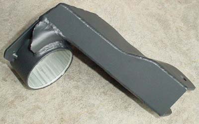
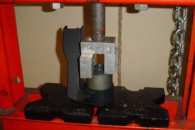
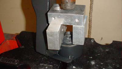
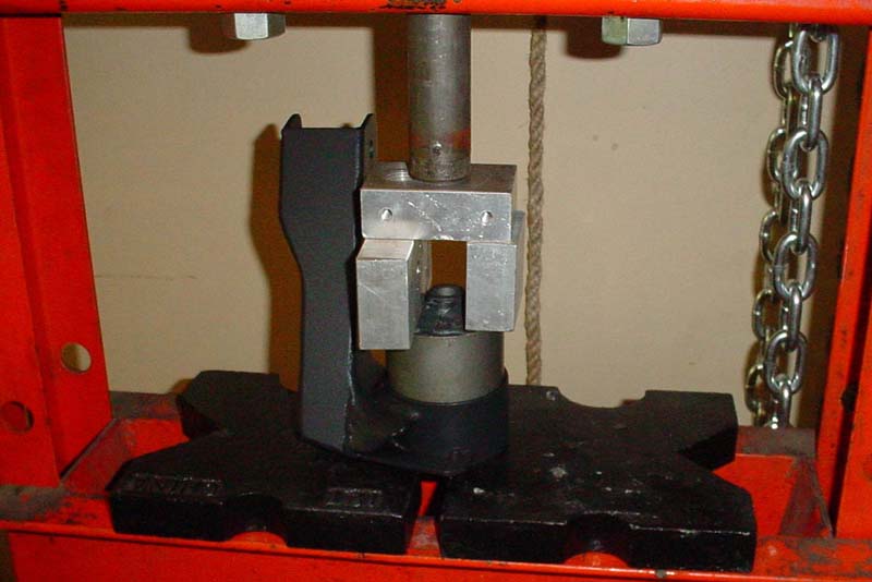
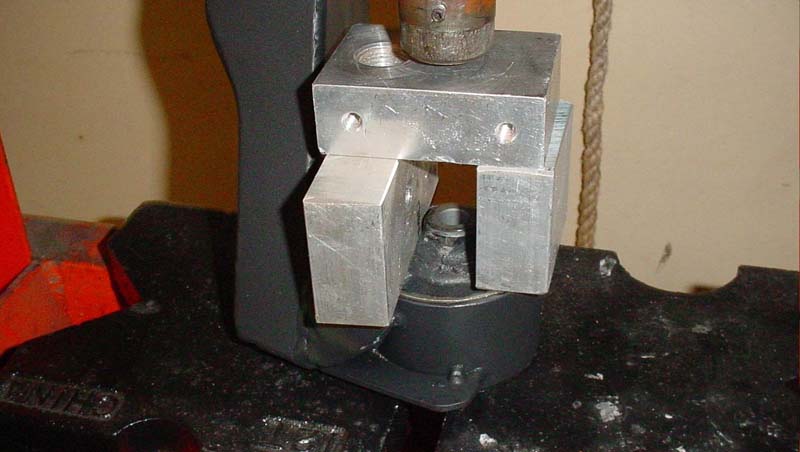
Yup....all done....all that is left to do is press in the new mount and everyone goes home happy!!!
Enter....the "orange beast".......
|
|
|
|
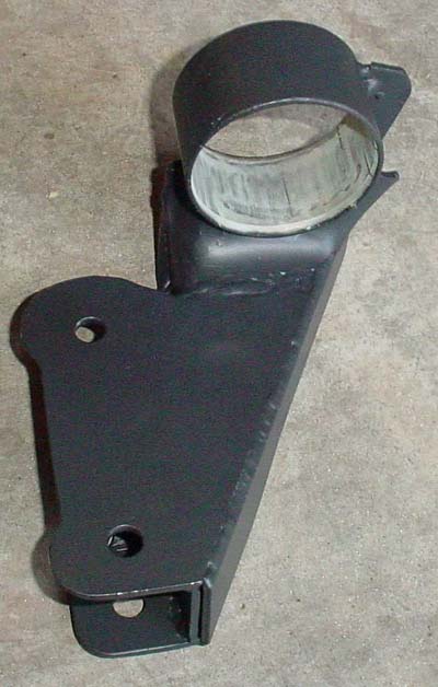
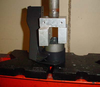
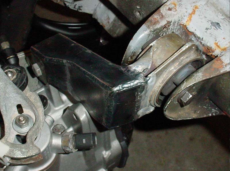
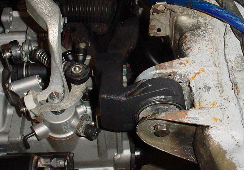
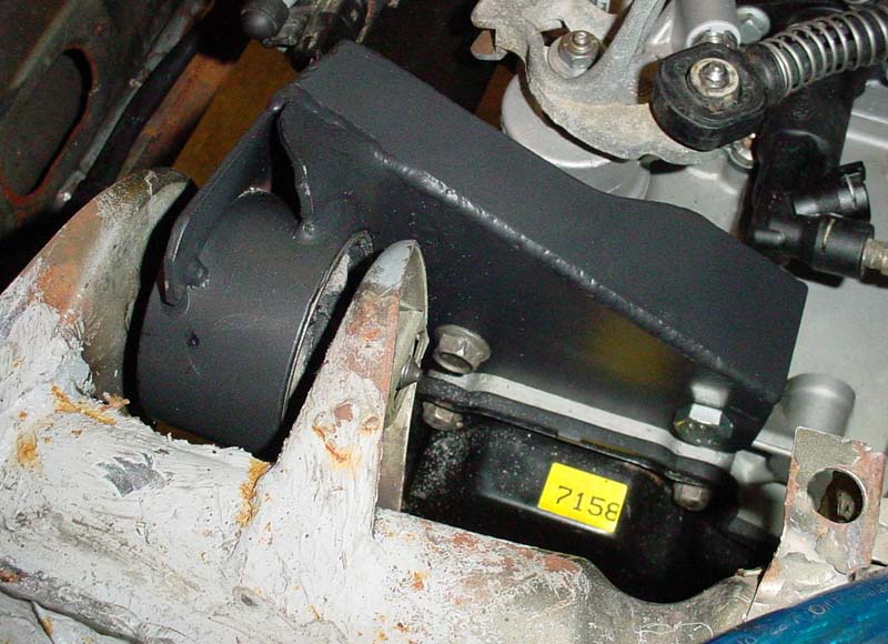
And finally the new motor mount can move into it's new home...gotta love Pascal's Principle!
|
|
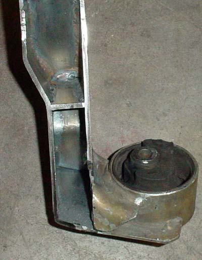
......and
here, many hours of work later, we have......the driver's side tranny
mount bracket with mount pressed in and aligned just perfectly.......
|
|

|
|

|
Done, done, done, done, done, done, done........done. Now....what was this about a rear mount bracket???
|


